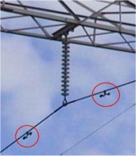
 Example of distribution line insulator: string of glass dishes
 Example of transmission line insulator: solid rod with rubber dishes
 Example of distribution line insulator: string of glass dishes Example of distribution line insulator: string of glass dishes | ");
InsulatorInfo.document.write(" Example of transmission line insulator: solid rod with rubber dishes Example of transmission line insulator: solid rod with rubber dishes | ");
InsulatorInfo.document.write("
| Guestbook | The Views | Links | Work on HV towers | Info on HV towers | Site-info | Sitemap |
 |
Magnificent Views Information on High Voltage Overhead Transmission and Distribution lines |
 |
Subjects:
What's in a tower?
About phases, circuits and shielding
How high is High? About different ways to express voltage
Electrical fields and induced voltage
Telecommunication on High Voltage Overhead lines
What's in a tower? Electrical insulation

Because the voltage of each phase is different from each other, and different from
ground (defined as zero voltage) all phase wires should be insulated from each other and
from ground. The insulation is accomplished by keeping enough distance (air) between the phases
and ground. The higher the voltage, the more distance is needed. The phase wires are
connected to the tower by an insulator or insulator string which is often made of glass,
ceramics or synthetic rubber. |
About phases, circuits and shielding
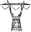
In the top, the tower has on both sides so called shield or ground wires. These wires protect the line from lightning strikes and are usually grounded in every tower. Below the ground wires on both sides of the tower the bundled phase wires (a bundle of two for each phase) are suspended from the tower by insulator strings. The phases of each circuit are attached on different sides of the tower. Click on the black or green parts of the tower (on the left or above) to find out more. |
About different ways to express voltageA high voltage line is normally designated by it's system voltage. This is the voltage between two phase wires of one circuit as RMS value. The voltage of a phase wire to ground is lower, and can be calculated here:
In the graph above all voltages are shown with the example of a 275 kV system voltage.
This system voltage results in a voltage difference between phase wires ranging from -200
to +200 kV. |
Electrical fields and induced voltage
The equipotential-lines, shown here on the left, connect points in space with the same
induced voltage (= potential) to each other. In the figure the value of the induced
voltage is given in kV (RMS value) next to the equipotential-lines. The graphical shape of
these lines depends on the shape and configuration of the tower, of course, and on how the
phases are distributed in the circuits. |

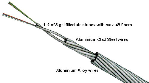
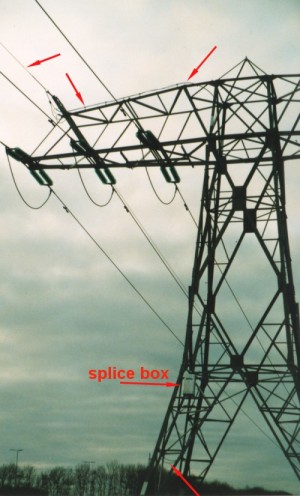
Telecommunication on High Voltage Overhead linesAll high voltage overhead lines are suitable also for carrying telecommunication traffic. This can be accomplished by installing optical fiber cables in the towers. Here at the right one of the possible cables is shown that can be installed in the towers. This one is a replacement for the shield wire and is called OPGW (Optical Powerline Ground Wire). Another well-known and often used cable is the ADSS (All Dielectric Self Supporting) optical fiber cable. Both cable types can carry up to 100 optical fibers and more. Each fiber can carry more than 10 Gigabits per second. For more information on cables that can be used in high voltage lines you can go to Draka Comteq.For more information on optical fibers go to Corning USA.  The picture on the left shows a 110 kV tower a little south of Appingedam, in the Netherlands, that carries a OPGW. The red arrows point to the OPGW. At the left leg in the front a splice box is located in which the optical fibers are spliced. |
For more information send an E-mail to: Arnie Berkers, 23-09-2002